| JOHN SAYERS PRODUCTIONS |
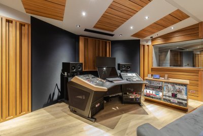
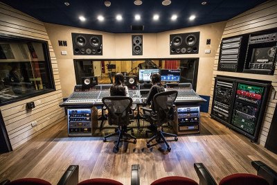
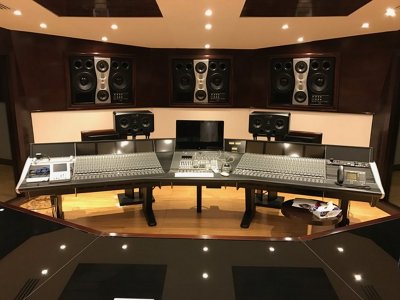
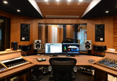
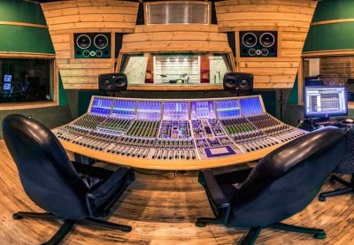
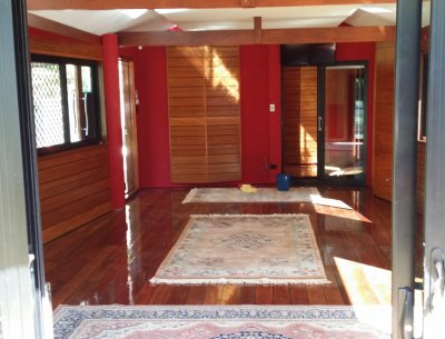
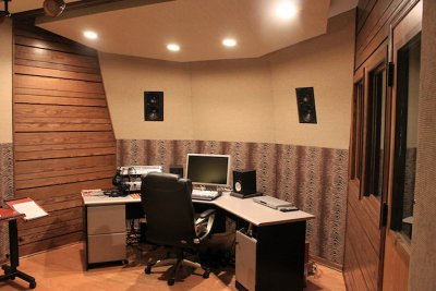
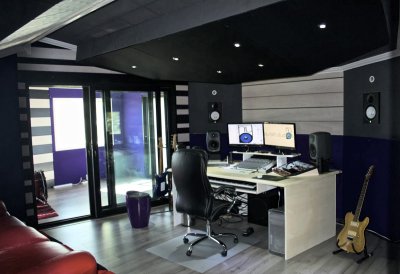
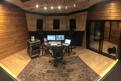
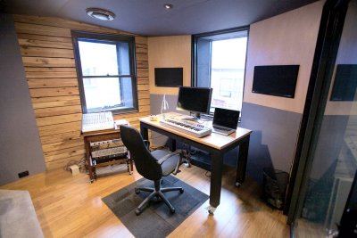
John Sayers Productions offer a complete recording studio design service. Our studios are represented worldwide in over 14 countries. All designs are created in Australia and studios are built using our comprehensive plans and ongoing internet consultation service.
read more...... |
|

|
STUDIO DESIGN FORUM |
The recording studio design forum is now in it's 10th year - it has over 130,000 posts, 15,000 topics and over 22390 members. It's the World's No 1 dedicated studio design forum.
sign up today |
. |